Introduction
From (Kalpakjian & Schmid, 2016):
In this chapter we will go over metalworking processes where the workpiece is subjected to plastic deformation, under forces applied through dies and tooling. Deformation processes generally are classified by type of operation as either primary working or secondary working; they are further divided into three categories of cold (room temperature), warm, and hot working.
Primary-working operation involve taking a solid piece of metal (generally from a cast state) and breaking it down successively into wrought material of various shapes by the basic processes of forging, rolling, extrusion, and drawing.
Secondary-working operation typically involve further processing of the products from primary working into final or semifinal products, such as bolts, gears, and sheet metal parts.
| Process | Description | Advantages | Applications |
|---|---|---|---|
| Forging | Deformation of metal using localized compressive forces, typically by hammering or pressing. It can be performed hot or cold, leading to different mechanical properties. | Produces parts with superior mechanical properties High strength due to grain refinement Less material waste | Crankshafts, gears, aerospace components, high-strength fasteners |
| Rolling | Metal is passed through a pair of rollers to reduce thickness or change cross-sectional shape. It can be done hot (hot rolling) or cold (cold rolling). | High production rate Good surface finish Can handle large pieces of metal Economical for mass production | Sheets, plates, I-beams, rails, automotive body panels |
| Extrusion | Metal is forced through a die to produce a continuous cross-sectional shape. Can be done hot or cold, and includes direct (forward) and indirect (backward) extrusion methods. | Ability to create complex cross-sections High material utilization Produces long lengths of uniform cross-sections Suitable for both metals and plastics | Pipes, tubing, structural shapes, window frames, heat sinks, electrical conduits |
Forging
Forging denotes a family of processes used to make discrete parts, in which plastic deformation is caused by compressive stresses applied through various dies and tooling. Forging is one of the oldest metalworking operations, dating back to 5000 B.C.
Open-Die Forging
Open-die forging typically involves hot working and large deformations using simple tools such as flat dies, rounded sections, punches, or saddles.
A common process, known as upsetting, involves placing a solid cylindrical workpiece (the blank) between two flat dies (platens) and reducing its height.
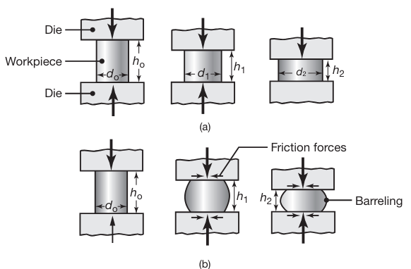
(a) Ideal deformation of a solid cylindrical specimen compressed between flat frictionless dies (platens), an operation known as upsetting. (b) Deformation in upsetting with friction at the die-workpiece interfaces. Note barreling of the billet caused by friction.
Because the volume of the cylinder remains constant in plastic deformation, any reduction in its height causes an increase in diameter. The reduction in height is defined as
where the subscript '
The engineering strain is
and the true strain
Barreling
In actual practice the specimen develops a barrel shape during upsetting, as shown in the following figure:
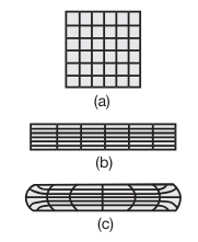
Schematic illustration of grid deformation in upsetting; (a) original grid pattern; (b) after deformation, without friction; and (c) after deformation, with friction. Such deformation patterns can be used to calculate the strains within a deforming body.
Barreling is caused primarily by frictional forces that oppose the radially outward flow of the material at the die-workpiece interfaces.
A result of barreling is that the deformation throughout the specimen becomes nonuniform or inhomogeneous
Forces under ideal conditions
If friction at the workpiece-die interfaces is zero and the material is perfectly plastic, with yield strength of
where
A typical true stress-true strain curve is shown in the following figure:
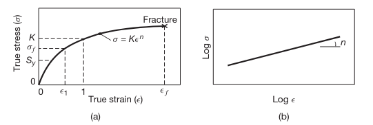
(a) True stress–true strain curve in tension. Note that, unlike in an engineering stress–strain curve, the slope is always positive and the slope decreases with increasing strain. Although in the elastic range stress and strain are proportional, the total curve can be approximated by the power expression shown. On this curve,
is the yield strength and is the flow stress. (b) True stress–true strain curve plotted on a log-log scale.
For convenience, such a curve is often approximated by the equation:
where the slope
If the material’s true stress-true strain curve is given by this equation, then the force at any stage during deformation becomes
where
For a work hardening material, the average flow stress is given by
We will sometimes assume the the material is rigid and perfectly plastic. For such material, once the stress reaches the yield strength
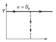
Schematic illustration of a rigid, perfectly plastic, idealized stress–strain curves.
Notes:
In the official course notes, there is no differentiation between
and , and denotes both of them with .
Slab Method of Analysis
There are several methods of analysis to theoretically determine stresses, strains, strain rates and forces in deformation processing. We will focus on the Slab method.
The slab method is one of the earlier and simpler methods of analyzing the stresses and loads in bulk-deformation processes. This method requires the selection of an element in the workpiece and identification of all the normal and frictional stresses acting on that element.
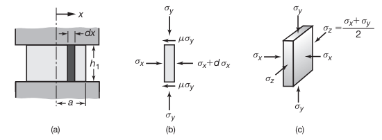
Stresses on an element in plane-strain compression (forging) between flat dies with friction. (Kalpakjian & Schmid, 2016).
After a lot of math, balancing forces, assuming
Isn't it supposed to be
? No Roma, it involves some assumptions about plastic deformation. Read the book, they explain everything in detail.
It can also be shown that the pressure
Where
Thus, the average pressure will be:
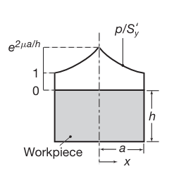
Distribution of die pressure, in dimensionless form of
, in plane-strain compression with sliding friction. Note that the pressure at the left and right boundaries is equal to the yield strength of the material in plane strain, .
For a disc-shaped cross section,
and the average pressure:
Example: Upsetting Force
A cylindrical specimen made of annealed 4135 steel has a diameter of
and is high. It is upset, at room temperature, by open-die forging with flat dies to a height of
Assuming that the coefficient of friction is, calculate the upsetting force required at the end of the stroke. Use the average-pressure formula. Solution:
The average-pressure formula is given bywhere
is replaced by because the workpiece material is strain hardening. For annealed 4135 steel, and . The absolute value of the true strain is and therefore
The final height of the specimen,
, is . The radius at the end of the stroke is found from volume constancy: Thus,
The upsetting force is
Impression-die forging
In impression-die forging, the workpiece acquires the shape of the die cavity (hence the term impression) while it is being deformed between the two closing dies.

Schematic illustrations of stages in impression-die forging. Note the formation of a flash, or excess material that subsequently has to be trimmed off.
Forces in impression-die forging can be difficult to predict, because of the generally complex shapes involved and the fact that each location within the workpiece is typically subjected to different strains, strain rates, and temperatures, as well as variations in coefficient of friction along the die-workpiece contact area. Certain empirical pressure-multiplying factors,
where
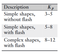
Range of
values for impression-die forging.
Rolling
Rolling is the process of reducing the thickness or changing the cross section of a long workpiece by compressive forces applied through a set of rolls.
Rolling, which accounts for about
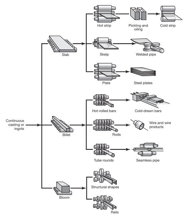
Schematic outline of various flat-rolling and shape-rolling operations.
Rolling is first carried out at elevated temperatures (hot rolling), wherein the coarse-grained, brittle, and porous cast structure of the ingot or continuously cast metal is broken down into a wrought structure, with finer grain size and improved properties
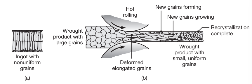
Changes in the grain structure of metals during hot rolling. This is an effective method to reduce grain size and refine the microstructure in metals, resulting in improved strength and good ductility.
Mechanics of Flat Rolling
The basic flat-rolling process is shown schematically in the following figure:
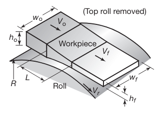
Schematic illustration of the flat-rolling process (Note that the top roll has been removed for clarity).
A strip of thickness
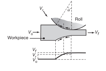
Relative velocity distribution between roll and strip surfaces. The arrows represent the frictional forces acting along the strip-roll interfaces. Note the difference in their direction in the left and right regions.
At one location along the arc of contact, however, the two velocities are the same; for this reason, this point is called the neutral point , neutral plane, or no-slip point. To the left of this point, the roll moves faster than the workpiece, and to the right, the workpiece moves faster than the roll.
Because of the relative motion at the interfaces, the frictional forces (which oppose motion) act on the strip surfaces in the directions shown in the last figure. In rolling, the frictional force on the left of the neutral point must be greater than the frictional force on the right. This difference results in a net frictional force to the right, making the rolling operation possible by pulling the strip into the roll gap.
Forward slip in rolling is defined as
and is a measure of the relative velocities at the exit of the work rolls.
Roll Pressure Distribution
It can be noted that the deformation zone in the roll gap is subjected to a state of stress similar to that in upsetting. However, the calculation of forces and stress distribution in rolling is more involved because the contact surfaces are curved. Also, in cold rolling, the material at the exit is strain hardened, and thus the flow stress at the exit is higher than that at the entry.
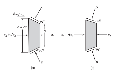
Stresses acting on an element in rolling: (a) entry zone and (b) exit zone.
It can be shown, that similar to upsetting, we can assume that
If we assume that the pressure distribution is symmetric, It can be shown that pressure distribution is given by (similar to Slab Method of Analysis in forging):
where
The average pressure distribution is given by:
If we don’t assume pressure distribution is symmetric, we get the following graph:
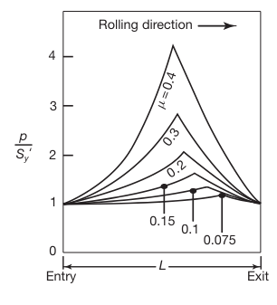
Pressure distribution in the roll gap as a function of the coefficient of friction. Note that as friction increases, the neutral point shifts toward the entry. Without friction, the rolls will slip, and the neutral point shifts completely to the exit.
Neutral Point Location
The neutral point (as explained in Rolling) is where the surface speed of the rolls matches the speed of the workpiece. The position of the neutral point depends on the balance of forward and backward friction forces. When friction increases, the force helping to move the workpiece through the rolls increases on the entry side. This enhanced frictional force shifts the neutral point toward the entry side because less force is needed to accelerate the workpiece to the roll speed.
Roll Forces
The roll force,
A simple method of calculating the roll force is to multiply the contact area by an average contact stress,
where
where
Roll Torque and Power
The roll torque,
The torque per roll is then
The power required per roll (usually there are 2 rolls, so just multiply by
where
Example: Power Required in Rolling
A
-wide 6061-O aluminum strip is rolled from a thickness of to . The roll radius is and the roll speed is .
Estimate the total power required for this operation.Solution: The length of the arc of contact,
is obtained by For 6061-O aluminum,
and . The true strain in this operation is Thus,
and,
Therefore, noting the width is
, Roll Forces yields so that the power per roll is
Therefore, the power needed for both rolls is
.
Extrusion
In the extrusion process developed in the late 1700s for producing lead pipe, a billet is placed in a chamber and forced through a die opening by a ram. The die may be round or of various shapes. Typical parts made are railings for sliding doors, window frames, aluminum ladders, tubing, and structural and architectural shapes.
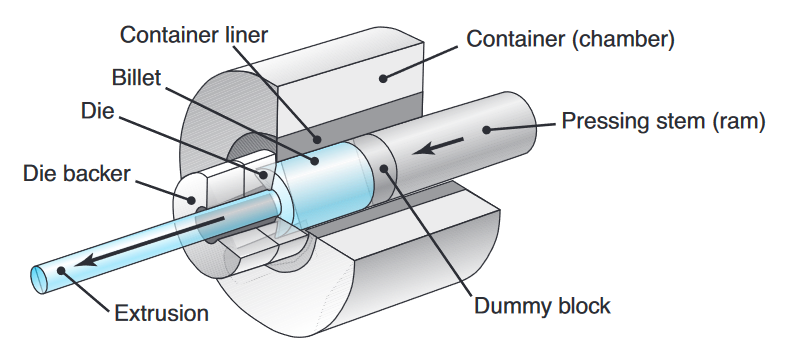
Schematic illustration of the direct-extrusion process. (Kalpakjian et al., 2014).
Two types of extrusions are direct and indirect extrusion:
- Direct extrusion (forward extrusion) is similar to forcing toothpaste through the opening of a tube. Note that the billet in this process moves relative to the container wall in the same direction as the extruded product.
- In indirect extrusion (reverse, inverted, or backward extrusion), the die moves toward the billet and there is no relative motion at the billet-container interface. Indirect extrusion is often used when the workpiece has a high level of friction with the billet, such as hot extrusion of steel.
Another important differentiation is between hot and cold extrusion processes:
- Hot extrusion: For metals and alloys that do not have sufficient ductility at room temperature, or in order to reduce the forces required, extrusion can be carried out at elevated temperatures.
- Cold extrusion: Developed in the 1940s, cold extrusion is a general term often denoting a combination of operations, such as a combination of direct and indirect extrusion and forging. The cold-extrusion process uses slugs cut from cold-finished or hot-rolled bars, wire, or plates.
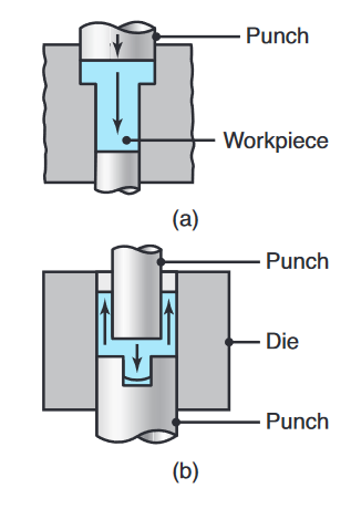
Two examples of cold extrusion; the arrows indicate the direction of metal flow during extrusion.
Mechanics of Extrusion
The force required for extrusion depends on (a) the strength of the billet material, (b) extrusion ratio, (c) friction between the billet, container, and die surfaces, and (d) process variables.

Process variables in direct extrusion; the die angle, reduction in cross-section, extrusion speed, billet temperature, and lubrication all affect the extrusion pressure. (Kalpakjian et al., 2014).
For a small die angle,
where
Extrusion Defects
Surface Cracking:
If extrusion temperature, friction, or speed is too high, surface temperatures can become excessive, which may cause surface cracking and tearing.
These cracks are intergranular (along the grain boundaries).
Surface cracking also may occur at lower temperatures, attributed to periodic sticking of the extruded part along the die land. Because of its similarity in appearance to the surface of a bamboo stem, it is known as a bamboo defect.
Internal Cracking:
The center of the extruded product can develop cracks, called center cracking, center-burst, arrowhead fracture, or chevron cracking:

Chevron cracking (central burst) in extruded round steel bars; unless the products are inspected, such internal defects may remain undetected and later cause failure of the part in service. (Kalpakjian et al., 2014).