Introduction
From (Kalpakjian & Schmid, 2016):
Machining processes are a critical component of manufacturing, used to shape and finish materials into precise and functional components. These processes involve removing material from a workpiece using various cutting tools and techniques to achieve desired dimensions, tolerances, and surface finishes. Machining is fundamental to the production of parts for a wide range of industries, including automotive, aerospace, electronics, and medical devices.
| Machining Process | Description | Notes |
|---|---|---|
| Turning | Performed on a lathe, turning involves rotating the workpiece against a single-point cutting tool to produce cylindrical shapes. | |
| Milling | In milling, a rotating multi-point cutting tool moves against the workpiece to remove material and create flat or contoured surfaces. | |
| Drilling | Drilling creates round holes in a workpiece using a rotating drill bit. | Not in syllabus |
| Grinding | Grinding uses an abrasive wheel to remove small amounts of material and achieve high surface finish and precision. | Not in syllabus |
| Broaching | Broaching involves pushing or pulling a multi-tooth cutting tool (broach) through a workpiece to remove material in a single pass. | Not in syllabus |
| Sawing | Sawing cuts material into smaller pieces using a saw blade with teeth. | Not in syllabus |
Turning
Turning is a fundamental machining process used in manufacturing to create cylindrical parts by removing material from a rotating workpiece using a cutting tool. This process is one of the most widely used and versatile methods in the manufacturing industry due to its ability to produce precise and intricate shapes with excellent surface finishes. Turning is typically performed on a lathe, which holds and rotates the workpiece against a single-point cutting tool that shapes the material.
Key Parameters and Equations
Examples of machining operations that can be performed on a lathe and similar machine tools.
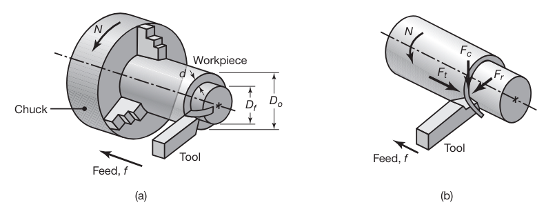
(a) Schematic illustration of a turning operation, showing depth of cut,
, and feed, . Cutting speed is the surface speed of the workpiece at the tool tip. (b) Forces acting on a cutting tool in turning. is the cutting force; is the thrust or feed force (in the direction of feed); and is the radial force that tends to push the tool away from the workpiece being machined. (Kalpakjian & Schmid, 2016).
-
Cutting Speed
is the speed at which the outer surface of the workpiece moves past the cutting tool, measured in meters per minute (m/min). It can be calculated as where
is the diameter of the workpiece and is the rotational speed. -
Feed Rate
is the distance that the cutting tool advances into the workpiece with each revolution, measured in millimeters per revolution . -
Depth of Cut
is the thickness of the material removed in one pass of the cutting tool, measured in millimeters . -
Cutting Time
is the time it takes to cut an long workpiece. It is given by If
is dynamic, we would need to integrate:
Example:
For a workpiece with a diameter of
meters rotating at :
- Material Removal Rate (
) quantifies the volume of material removed from a workpiece per unit time. A higher MRR indicates a more efficient process, but it must be balanced with considerations of tool wear, surface finish, and accuracy.
Cutting Force and Power
The cutting force
where
The power
where
Straight Turning and Facing
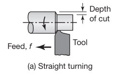
Straight turning is a machining process performed on a lathe where a single-point cutting tool moves parallel to the axis of a rotating cylindrical workpiece. The primary purpose of straight turning is to reduce the diameter of the workpiece to achieve a desired dimension and surface finish.
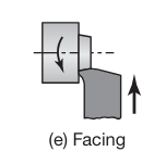
Facing is a machining process also performed on a lathe, where the cutting tool moves perpendicular to the axis of a rotating cylindrical workpiece. The goal of facing is to produce a flat surface at the end of the workpiece.
Surface Finish and Surface Integrity
Surface finish describes the geometric features of surfaces, whereas surface integrity pertains to properties that are strongly influenced by the type of surface produced.
Built-up edge and depth of cut can adversely affect surface finish and integrity. A shallow depth of cut (or dull tool) can also compromise surface finish. A dull cutting tool has a larger radius along its edges, just as a dull pencil or knife does.
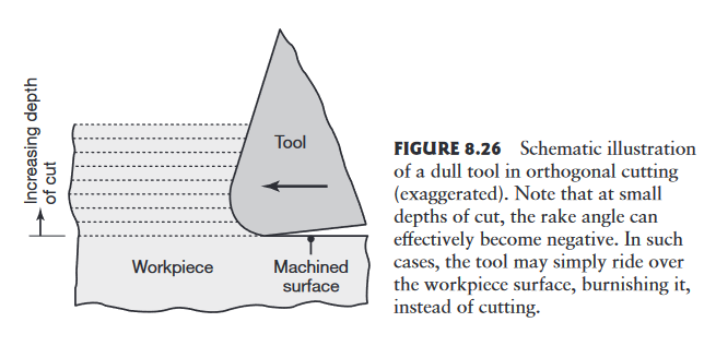
Schematic illustration of a dull tool in orthogonal cutting (exaggerated). Note that at small depths of cut, the rake angle can effectively become negative. In such cases, the tool may simply ride over the workpiece surface, burnishing it, instead of cutting. (Kalpakjian & Schmid, 2016).
If the radius is large in relation to the depth of cut, the tool will rub over the machined surface, generating frictional heat, inducing surface residual stresses, and causing surface damage, such as tearing and cracking.
In practice, the depth of cut should generally be greater than the radius on the cutting edge.
Feed marks:
In turning, as in some other machining operations, the cutting tool leaves a spiral profile (feed marks) on the machined surface as it moves across the workpiece.
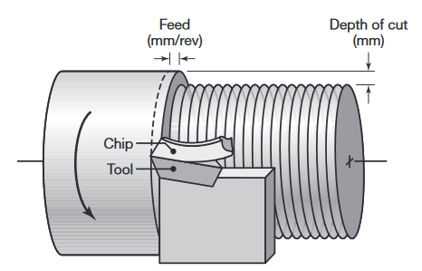
Terminology used in a turning operation on a lathe, where f is the feed (in mm/rev) and d is the depth of cut. (Kalpakjian & Schmid, 2016).
As expected, the higher the feed,
The total roughness height,
where
The Arithmetic Mean Roughness,
Milling
Milling is a machining process that involves the use of rotary cutters to remove material from a workpiece. The milling process can create a variety of features including flat surfaces, slots, and complex contours. The workpiece is usually held stationary while the cutting tool rotates and moves across the material to achieve the desired shape.
Types of milling operations:
- Face Milling: Produces flat surfaces by cutting with the end of the milling cutter.
- Peripheral Milling/Slab Milling: Involves cutting along the periphery of the cutter, used for creating deep slots, threads, and gear teeth.
- End Milling: Utilizes an end mill cutter to produce complex shapes, slots, and holes.
Key Parameters and Equations
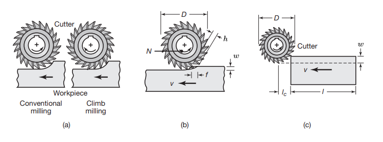
(a) Illustration showing the difference between conventional milling and climb milling. (b) Slab-milling operation, showing width of cut,
; feed per tooth, ; chip depth of cut, and workpiece speed, . (c) Schematic illustration of cutter travel distance, , to reach full depth of cut. (Kalpakjian & Schmid, 2016).
-
Cutting Speed
is calculated in the same way as [[#Turning#Key Parameters and Equations|turning]]: where
is the diameter of the workpiece and is the rotational speed. -
Feed Rate
: The feed rate is the distance the tool advances during one revolution of the spindle. As opposed to turning, we like to analyze the cutting process per teeth - so we define - feed per tooth. Therefore: where
is feed per tooth ; and is number of teeth on the cutter. -
Width of Cut
is the thickness of the material removed in one pass of the cutting tool, measured in millimeters .
Note that the thickness of the chip in slab milling varies along its length, because of the relative longitudinal movement between the cutter and the workpiece.
-
Chip Thickness
is the thickness of the material cut by a single tooth of the milling cutter. It can be influenced by the feed per tooth , and the entry angle of the tooth into the material . -
Workpiece Speed
is the speed of the workpiece. It is given by -
Cutting Time
is the time it takes to cut an long workpiece. It is given by
Some other common parameters are related to the number of teeth in the milling cutter:
- Engagement angle
is the arc of the cutter that is in contact with the workpiece, measured between the entry and exit points of the cutter during the milling operation. - Tooth pitch angle
is the angle between the cutting edges of two adjacent teeth on the circumference of the milling cutter. This angle is related to the number of teeth on the cutter. - Number of teeth
is the number of teeth in the milling cutter, and is simply given by: - Number of effective teeth
is the number of teeth engaged with the workpiece at any given time during milling, and its average is given by:
$$
\boxed {
n=\dfrac{\alpha}{\beta}
} - Material Removal Rate (
) for milling is given by: where is the width of the cut, which is the same the workpiece width if is narrower than the cutter. is the linear speed of the workpiece, and is the depth of cut.
Cutting Force and Power
The cutting force
or, its average for a whole width of cut
where
The average power
where
The power at any given time can be calculated using:
Exercises
Question 1
A
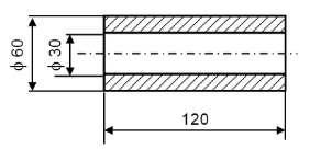
Schematic of the workpiece after the desired facing cut
In addition, the outer diameter is
Part a
Given two cutting tools,
Which cutting tool should be used to make the desired cut?
Solution:
First, we will try to guess which rotational speed
but,
- For cutting tool
:
The optimal rotational speed is approximately:Now, if we actually try to use the rotational speed, by substituting the maximum and minimum of , we get: Which is outside the optimal bounds for . - For cutting tool
:
The optimal rotational speed is approximately:Now, if we actually try to use the rotational speed, by substituting the maximum and minimum of , we get: Which is within the optimal bounds for .
Therefore, we can conclude that cutting tool
Part b
How long will the cutting operation be, using the cutting tool we chose?
Solution:
For cutting tool
Therefore, we get:
Parc c
Given that the machine used, outputs (in terms of cutting power)
Given: the material’s specific cutting force is
Solution:
We know that the maximum cutting speed for cutting tool
And the maximum power:
Therefore, cutting tool
Question 2
Given the following parameters:
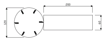
Schematic of the cutting tool and workpiece
Part a
Find
Solution:
According to [[#Milling#Key Parameters and Equations|cutting speed]], we get:
Substituting the given parameters:
Part b
At which point will the force be maximal and at which point minimal?
Solution:
From the schematic, we can see that there will always be only one tooth in the material at any given time:
The dimensions of the workpiece and the cutting tool align perfectly
Therefore, it is enough to use the [[#Milling#Cutting Force and Power|cutting force]] (per tooth) formula to calculate the maximum and minimum cutting force:
We get maximum for
Part c
Calculate the minimum and maximum forces.
Solution:
Pard d
Find the maximum power required.
Solution:
According to [[#Milling#Cutting Force and Power|power of cutting tool]]:
Part e
Find the average power required.
Solution:
To find the average power we can treat the entire tool as a single cutting implement with a width of
The average [[#Milling#Cutting Force and Power|cutting force]]:
Therefore, the average power: